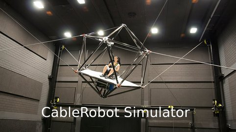
The CableRobot Simulator
The CableRobot Simulator provided a novel approach to the design of motion simulation platforms, as it used cables and winches for actuation instead of rigid links known from hexapod simulators. This approach allowed reducing the actuated mass, to scale up the workspace significantly, and provided great flexibility to switch between system configurations in which the robot could be operated. The simulator was used for studies in the fields of human perception and cognition research, flight simulation, and virtual reality applications.
The CableRobot simulator used a parallel kinematics architecture, where the links that are rigid on other simulators were replaced by winch driven cables. While some research institutes work in the field of cable-driven parallel robots, no-one had so far developed a system for the safe transport of passengers with a focus on high performance motion simulation.
By using a cable robot design, we were able to build a motion simulator with an extraordinary power-to-weight ratio of approximately 2.6kW/kg. The simulator was operated at a maximum acceleration of 5m/s2 in a workspace of 5x6x4 m3, and maximum roll, pitch and yaw angles of ±40º, ±40º, ±5º respectively.
Using winches with a total power of 384 kW allowed for cable forces of 12000N and a maximum acceleration of 14 m/s2 at a payload of 200 kg. The bandwidth of the system varied between 10 and 14 Hz depending of the cable length and cabin position inside the workspace.
The simulator cabin design was optimized with regards to stability, cabin volume, and weight. Using an icosahedron truss structure allowed to minimize the weight while maximizing the cabin volume, since it provided the optimal use of components regarding the tension flow through the structure. On the other side it provided an optimal relation of nodes and edges with regards to a sphere enclosure. Using carbon fiber rods for the edges and aerospace alloy for the nodes kept the weight below 80 kg for the whole cabin without instrumentation. For the cable topology a cross over configuration as shown in the figures was chosen to maximize the pitch and roll capability of the cabin.
